For prototyping, i.e. for testing projects based on e.g. Arduino, contact boards are very often used. Why? Because at the stage of testing your ideas you do not have to solder anything, connect to each other permanently. This is what a contact or prototyping board is for. It consists of many holes to which you can connect diodes, wires, sensors and other electronic elements.
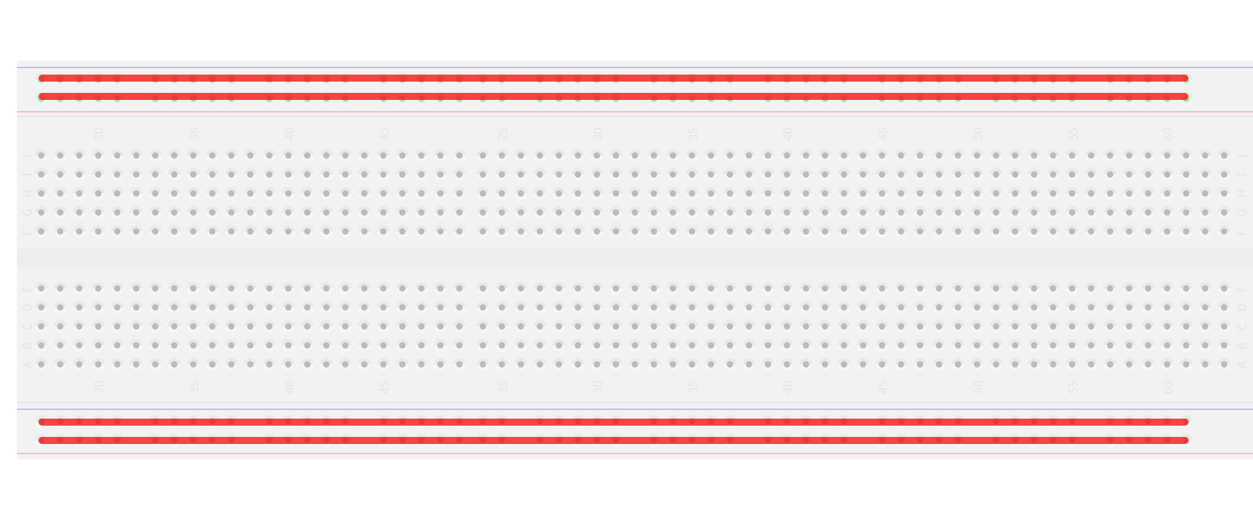
PCBs have different sizes. Most often they consist of 30 or 60 rows. On both sides of the board there are rails that are used to distribute power and ground across the board. These are marked plus and minus.
how to distribute the voltage and mass
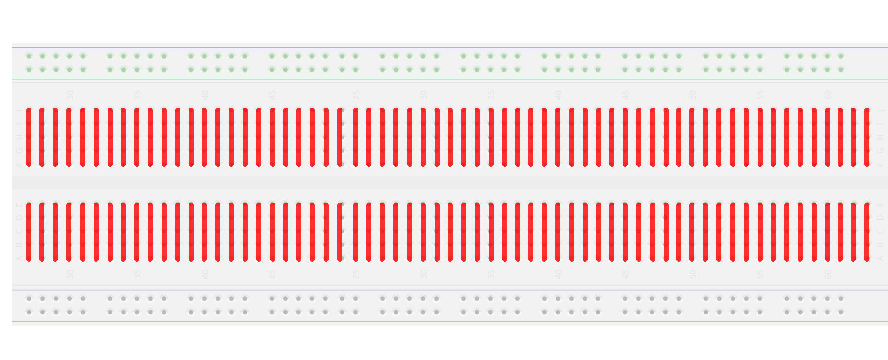
Regardless of where you connect the wire, mass or voltage will be available in each hole across the width of the board. The inner part of the board, which is used to connect e.g. diodes, sensors is connected this way:
the holes are connected to each other vertically
Connection wires
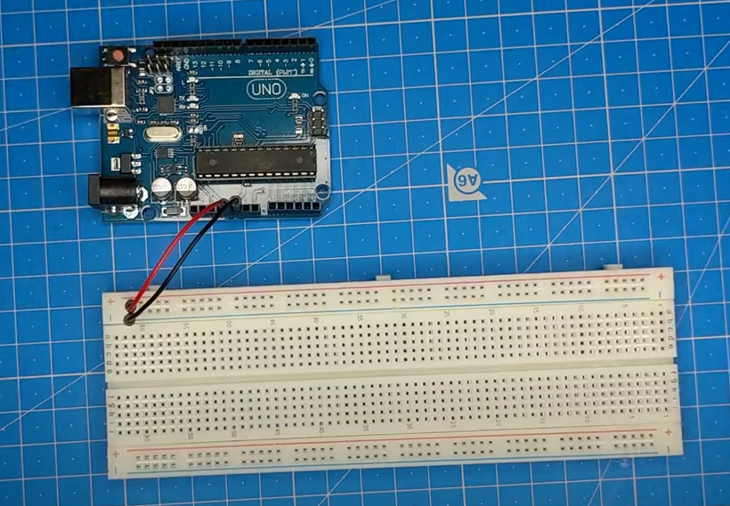
When you want to create a new electronic circuit you need to start by preparing a schematic and the components of the circuit you want to place on our board. For prototyping purposes, you can easily place your components in the holes of the board using wires.
There is no need to use any special tools such as soldering irons when working with contact boards.
Connection wires are extremely useful when prototyping. They are available at any electronics store or simply at sites like Allegro. It should be noted here that these wires are extremely cheap.
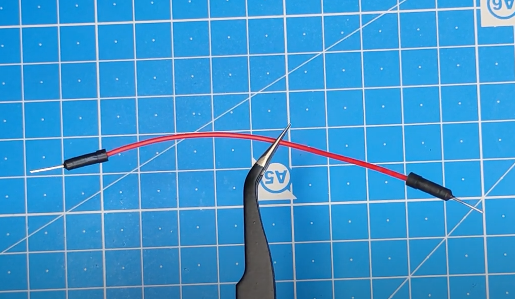
“male-male” cable
Wires used in prototyping have connecting pins at each end. This allows them to be used to connect two points without soldering. Wires come in different lengths and colors. The colors don’t really matter but it’s accepted that red wires are used for voltage and black ones for ground.
The wires come in three versions: “male-male”, “female-female” and “male-female”. The male-male version is the most commonly used, because its ends have pins that can be plugged into holes on the contact board and into the female ends of another jumper.
Founder of Dogtronic. IT specialist with several years of experience. Enthusiast of electronics and blockchain technology. Author of the course "Basics of robotics".